Contents
Introduction
This document explains the Spanning Tree Protocol (STP) root guard feature. This feature is one of the STP enhancements that Cisco created. This feature enhances switched network reliability, manageability, and security.Prerequisites
Requirements
There are no specific requirements for this document.Components Used
This document is not restricted to specific software and hardware versions.Conventions
Refer to Cisco Technical Tips Conventions for more information on document conventions.Feature Description
The standard STP does not provide any means for the network administrator to securely enforce the topology of the switched Layer 2 (L2) network. A means to enforce topology can be especially important in networks with shared administrative control, where different administrative entities or companies control one switched network.The forwarding topology of the switched network is calculated. The calculation is based on the root bridge position, among other parameters. Any switch can be the root bridge in a network. But a more optimal forwarding topology places the root bridge at a specific predetermined location. With the standard STP, any bridge in the network with a lower bridge ID takes the role of the root bridge. The administrator cannot enforce the position of the root bridge.
Note: The administrator can set the root bridge priority to 0 in an effort to secure the root bridge position. But there is no guarantee against a bridge with a priority of 0 and a lower MAC address.
The root guard feature provides a way to enforce the root bridge placement in the network.
The root guard ensures that the port on which root guard is enabled is the designated port. Normally, root bridge ports are all designated ports, unless two or more ports of the root bridge are connected together. If the bridge receives superior STP Bridge Protocol Data Units (BPDUs) on a root guard-enabled port, root guard moves this port to a root-inconsistent STP state. This root-inconsistent state is effectively equal to a listening state. No traffic is forwarded across this port. In this way, the root guard enforces the position of the root bridge.
The example in this section demonstrates how a rogue root bridge can cause problems on the network and how root guard can help.
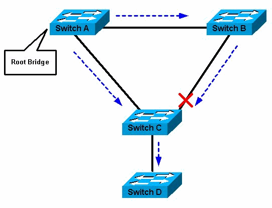
In Figure 1, Switches A and B comprise the core of the network, and A is the root bridge for a VLAN. Switch C is an access layer switch. The link between B and C is blocking on the C side. The arrows show the flow of STP BPDUs.
Figure 1
In Figure 2, device D begins to participate in STP. For example, software-based bridge applications are launched on PCs or other switches that a customer connects to a service-provider network. If the priority of bridge D is 0 or any value lower than the priority of the root bridge, device D is elected as a root bridge for this VLAN. If the link between device A and B is 1 gigabit and links between A and C as well as B and C are 100 Mbps, the election of D as root causes the Gigabit Ethernet link that connects the two core switches to block. This block causes all the data in that VLAN to flow via a 100-Mbps link across the access layer. If more data flow via the core in that VLAN than this link can accommodate, the drop of some frames occurs. The frame drop leads to a performance loss or a connectivity outage.
Figure 2
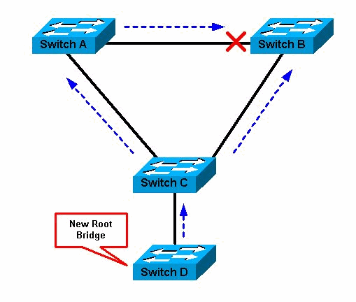
The root guard feature protects the network against such issues.
The configuration of root guard is on a per-port basis. Root guard does not allow the port to become an STP root port, so the port is always STP-designated. If a better BPDU arrives on this port, root guard does not take the BPDU into account and elect a new STP root. Instead, root guard puts the port into the root-inconsistent STP state. You must enable root guard on all ports where the root bridge should not appear. In a way, you can configure a perimeter around the part of the network where the STP root is able to be located.
In Figure 2, enable root guard on the Switch C port that connects to Switch D.
Switch C in Figure 2 blocks the port that connects to Switch D, after the switch receives a superior BPDU. Root guard puts the port in the root-inconsistent STP state. No traffic passes through the port in this state. After device D ceases to send superior BPDUs, the port is unblocked again. Via STP, the port goes from the listening state to the learning state, and eventually transitions to the forwarding state. Recovery is automatic; no human intervention is necessary.
This message appears after root guard blocks a port:
%SPANTREE-2-ROOTGUARDBLOCK: Port 1/1 tried to become non-designated in VLAN 77.
Moved to root-inconsistent state
Availability
Root guard is available in Catalyst OS (CatOS) for Catalyst 29xx, 4500/4000, 5500/5000, and 6500/6000 in software version 6.1.1 and later. For the Catalyst 6500/6000 that runs Cisco IOS® system software, this feature was first introduced in Cisco IOS Software Release 12.0(7)XE. For the Catalyst 4500/4000 that runs Cisco IOS system software, this feature is available in all releases.For the Catalyst 2900XL and 3500XL switches, root guard is available in Cisco IOS Software Release 12.0(5)XU and later. The Catalyst 2950 series switches support the root guard feature in Cisco IOS Software Release 12.0(5.2)WC(1) and later. The Catalyst 3550 series switches support the root guard feature in Cisco IOS Software Release 12.1(4)EA1 and later.
Configuration
CatOS Configuration
The root guard configuration is on a per-port basis. On Catalyst switches that run CatOS, configure root guard in this way:In order to verify whether the root guard is configured, issue this command:vega> (enable) set spantree guard root 1/1 Rootguard on port 1/1 is enabled. Warning!! Enabling rootguard may result in a topology change. vega> (enable)
vega> (enable) show spantree guard
Port                     VLAN Port-State    Guard Type
------------------------ ---- ------------- ----------
 1/1                     1    forwarding          root
 1/2                     1    not-connected       none
 3/1                     1    not-connected       none
 3/2                     1    not-connected       none
 3/3                     1    not-connected       none
 3/4                     1    not-connected       none
 5/1                     1    forwarding          none
 5/25                    1    not-connected       none
15/1                     1    forwarding          none
vega> (enable)
Cisco IOS Software Configuration for Catalyst 6500/6000 and Catalyst 4500/4000
On the Catalyst 6500/6000 or Catalyst 4500/4000 switches that run Cisco IOS system software, issue this set of commands in order to configure STP root guard:Note: Cisco IOS Software Release 12.1(3a)E3 for the Catalyst 6500/6000 that runs Cisco IOS system software changed this command from spanning-tree rootguard to spanning-tree guard root. The Catalyst 4500/4000 that runs Cisco IOS system software uses the spanning-tree guard root command in all releases.Cat-IOS# configure terminal Enter configuration commands, one per line. End with CNTL/Z. Cat-IOS#(config)# interface fastethernet 3/1 Cat-IOS#(config-if)# spanning-tree guard root
Cisco IOS Software Configuration for Catalyst 2900XL/3500XL, 2950, and 3550
On the Catalyst 2900XL, 3500XL, 2950, and 3550, configure switches with root guard in interface configuration mode, as this example shows:Hinda# configure terminal Enter configuration commands, one per line. End with CNTL/Z. Hinda(config)# interface fastethernet 0/8 Hinda(config-if)# spanning-tree rootguard Hinda(config-if)# ^Z *Mar 15 20:15:16: %SPANTREE-2-ROOTGUARD_CONFIG_CHANGE: Rootguard enabled on port FastEthernet0/8 VLAN 1.^Z Hinda#
What Is the Difference Between STP BPDU Guard and STP Root Guard?
BPDU guard and root guard are similar, but their impact is different. BPDU guard disables the port upon BPDU reception if PortFast is enabled on the port. The disablement effectively denies devices behind such ports from participation in STP. You must manually reenable the port that is put into errdisable state or configure errdisable-timeout.Root guard allows the device to participate in STP as long as the device does not try to become the root. If root guard blocks the port, subsequent recovery is automatic. Recovery occurs as soon as the offending device ceases to send superior BPDUs.
For more information about BPDU guard, refer to this document:
Does the Root Guard Help with the Two Roots Problem?
There can be a unidirectional link failure between two bridges in a network. Because of the failure, one bridge does not receive the BPDUs from the root bridge. With such a failure, the root switch receives frames that other switches send, but the other switches do not receive the BPDUs that the root switch sends. This can lead to an STP loop. Because the other switches do not receive any BPDUs from the root, these switches believe that they are the root and start to send BPDUs.When the real root bridge starts to receive BPDUs, the root discards the BPDUs because they are not superior. The root bridge does not change. Therefore, root guard does not help to resolve this issue. The UniDirectional Link Detection (UDLD) and loop guard features address this issue.
For more information on STP failure scenarios and how to troubleshoot them, refer to this document:
No comments:
Post a Comment