Friday, July 31, 2015

InfiniBand improves efficiencies

Several server trends are driving the increased demand for I/O bandwidth: the arrival of multicore CPUs, use of virtualization (driving up server utilization), powerful new cluster applications, increased reliance on networked storage and the rise of blade servers.
security tools 1
There’s no silver bullet, so load up with as many of these as you can.
Read Now
With high bandwidth and end-to-end latency in the range of 1 microsecond, 20Gbps InfiniBand (commonly called DDR, or double data rate) is helping to address data center I/O challenges and is rapidly gaining acceptance in high-performance computing centers.
InfiniBand connectivity
InfiniBand is a standard defined by the InfiniBand Trade Association and supported by many vendors and the Open Fabrics Alliance, an open source software community.
The standard defines several key technologies that help it deliver high performance and reliability with low latency: credit-based flow control, channelized I/O with hardware-based QoS, and a transport optimized for moving massive amounts of traffic with minimal load on the server.
Many network protocols have the ability to retransmit dropped packets, usually at the transport layer, but communications typically is slowed by these protocols to ensure recovery, severely degrading performance.
Most packet loss in an Ethernet network occurs when network equipment is heavily congested and buffer space becomes full: Packets are dropped because the speed of the traffic is too high to stop the transmitting source in time.
InfiniBand uses a credit-based, flow-control mechanism to ensure the integrity of the connection, so packets rarely are dropped. With InfiniBand, packets will not be transmitted until there is verified space in the receiving buffer. The destination issues credits to signal available buffer space, after which the packets are transmitted. This eliminates congestion as a source of packet loss, greatly improving efficiency and overall performance.
InfiniBand also uses strict QoS controls implemented in hardware. When multiple servers share network resources, it's important to prevent a flood of low-priority traffic from blocking time-sensitive traffic, and the problem is compounded when multiple virtual servers are implemented on a group of servers.
InfiniBand's credit-based flow control is provided separately across many channels, providing a simple yet robust QoS mechanism for protecting traffic. Traffic protection is critical for converged wire strategies because it lets a single interconnect replace multiple, parallel networks required for clustering, storage, communications and management traffic. It also is critical for virtualized environments.
Because InfiniBand was designed to connect servers and storage efficiently in close proximity, the InfiniBand transport protocol was optimized for this environment. TCP, on the other hand, is the most ubiquitous transport protocol - implemented on devices ranging from refrigerators to supercomputers - but generality comes at a price: It is complex, the code is large and full of special cases, and it's difficult to offload. InfiniBand transport was defined later, during the era of multigigabit networking and high-performance servers, and is more streamlined, making it suitable for offloading to purpose-built, efficient hardware adapters. Offloading the InfiniBand transport enables very high performance with minimal load on the host CPU, so the CPU can focus on useful application processing.
However, most users of InfiniBand also run TCP/IP for application compatibility. Some traffic between servers requires the performance and offloading of the InfiniBand transport, while other traffic requires the protocol and application compatibility provided by TCP/IP. Many InfiniBand-powered data centers use both.
As the technology behind InfiniBand becomes more familiar, the benefits in performance, cost savings and scaling are being applied to a wider variety of applications, both in technical clusters and in the data center. InfiniBand is an example of a technology that is a perfect fit for the server and storage interconnect challenges for which it was conceived.
Tuchler is senior director, product management at Mellanox Technologies. He can be reached at dan@mellanox.com.

Thursday, July 30, 2015

Cluster Lifecycle Management: Recycle and Rebirth

three-rack cluster In the previous Cluster Lifecycle Management column, I examined the various options for Capacity Planning and Reporting that can help you prepare for the inevitability of upgrading or refreshing your HPC cluster. In this column, we wrap up the Cluster Lifecycle Management series by discussing how you should actually go about upgrading or perhaps even replacing the system.
I focused quite a bit in this column series on the steps that need to be taken to keep your system running efficiently so that end users have productive experiences and your organization gains a positive ROI on its investment in HPC technology. But even with your clusters running at peak efficiency, the day will come – could be within a few months or could be four years – when you will start seeing the need to upgrade the system.
In the Capacity Planning and Reporting column, I stressed the need for a solid reporting system that keeps the HPC manager up to date regarding how the clusters are being used, and how they are performing. This is important because a system refresh, whether big or small, can’t be a snap decision. Budgeting for and procuring the new resources require a long lead time and must follow a thorough examination of how the system has been used to date. Having the usage and performance history is critical to making good decisions regarding upgrades and changes.
Symptoms that indicate change is needed will come in various forms and severities. Most commonly, your business has grown and users are asking for more speed, or more throughput, or additional storage to complete their jobs. Or perhaps the software applications have evolved and need additional compute capacity or even a different software stack to run effectively. After a couple of years, hardware can simply get out of date and can’t keep up with required throughput or can become significantly more expensive to operate and maintain. Associated symptoms include more frequent hardware failures, more unexplained intermittent job failures, etc.
Having the system and job usage and performance reporting system, in combination with a trouble-ticketing and change management system, will provide you the data you need to make data driven analytical decisions as to which options are the best ones to take. As always, very seldom is there only one path!
System upgrades and refreshes come in varying degrees. Just like making a decision on buying a car – do you replace the old one, or just upgrade/repair some parts, or buy a new one and keep the old one – cluster refreshes are no different. However, the decision is not to be taken lightly due to the cost involved with each of the alternatives. Generally speaking, the options are to upgrade existing system, or to expand the existing cluster by adding additional compute and/or storage, or to replace the entire system. In my experience with scores of customers or upgrades, rolling upgrades seem the most common where customers are able to keep certain production volume going while upgrading some parts of the system.
To determine which path to take, you’ll need to refer to the historical reporting information I recommended you maintain from the start of operations. Knowing what hardware to upgrade or replace will be dictated by the metrics of how your system has been used. These metrics will help you make a decision that provides the best ROI, as was your original decision to deploy HPC technology in the first place.
Some important information, or metrics, that you’ll have to examine include the following:
  • What is the average throughput of your system?
  • What is the usage profile?
  • What applications run most efficiently on which architectures?
  • Which nodes are used the most? The least?
  • What problems are your users reporting?
  • What are the costs associated with maintenance, administration, power, and software licenses?
Your job is to perform a cost-benefit analysis using these data points so you can determine which option will yield the best return to the organization. And most importantly, your enhanced system should serve the end users more effectively and reliably than ever before. Just as you did before purchasing your first cluster, you must assess your upgrade needs based on your current and expected usage profile.
Once the decision has been made on what to replace or acquire, you must crank up the RFP (Request For Proposal) process that you used to buy the original system. If possible, put the same team together – system administrators, datacenter operators, end users, IT staff, and executives, and engage them in the analysis and acquisition process again. If you weren’t happy with the architecture or performance of your original system, you have the opportunity now to enact changes that will improve your cluster in its second incarnation. One major consideration with a new system RFP is to ensure compatibility of the new system with existing one is taken into account. This includes management systems, schedulers, software and your workflows and policies and procedures.
Even if you had a positive experience with your original HPC purchase and want to buy from the same vendor again, I still recommend sending at least two or three other RFPs out. In today’s rapidly changing technological landscape, you might be surprised to find a different vendor now offers exactly what you need at a better value. Notice I said value not price! A good vendor with knowledge of your existing system can provide valuable insight into what options may or may not be a good choice.
Just as your original RFP took into account deployment of the new system, your upgrade must be installed, deployed and validated by a seasoned professional. Upgrades, especially major, require a unique skill set because they must be accomplished with minimal disruption to the existing system. If the old system will be replaced entirely, logistics can become a problem and must be handled in the RFP. All of the implementation activities add ‘soft’ dollars to the cost of the upgrade and must be taken into account in the cost-benefits analysis.
Finally, what will you do with the old hardware or entire system you are replacing? Depending on the age and condition, you might want to consider donating to a local college or even selling the system to another organization.
Once the upgrade or replacement is up and running, the rebirth of your HPC system is complete, for now. You’ll know the refresh has been a success if you see improvements in key metrics – throughput has increased, jobs running to completion and overall operations costs coming down. And most importantly, you should see greater satisfaction and fewer complaints from your end user.
Celebrate when you are done as this process is not easy – it often feels like replacing the tires on a moving car! But is that not why you enjoy the HPC world? It is not for the faint of heart. Nice work! Now lather, rinse and repeat. Happy clustering.

Cluster Lifecycle Management: Capacity Planning and Reporting

 clusters
In the previous Cluster Lifecycle Management column, I discussed the best practices for proper care and feeding of your cluster to keep it running smoothly on a daily basis. In this column, we will look into the future and consider options for making sure your HPC system has the capacity to meet the needs of your growing business.
I wrapped up the Care and Feeding column by noting how critical it is to monitor the HPC system as a routine part of daily operations to detect small problems before they become big ones. This concept of gathering system data dovetails with capacity planning and reporting because the information you collect each day will paint an overview of larger operational trends over time that help you plan for the future.
An HPC system is not static. In fact, most will need to undergo major upgrades, expansions or refreshes after two to three years. And in all likelihood, these changes will be prompted by new demands put on the system related to growth in your business. New users and new projects will require changes and upgrades. Or in some cases, new or upgraded applications may require more processing capacity.
Perhaps most often, the trigger that prompts a capacity upgrade is related to data. In today’s world, the problems being solved by the HPC cluster are getting bigger and more complicated, requiring the crunching of larger and more complex data sets. Adding capacity is sometimes the only way to keep up.
Monitoring and reporting can tell you how efficiently the processes and applications are running, but the information must be analyzed to determine how busy the system is overall. These details can help you make better decisions on upgrading and changing the system. Specifically, you need to anticipate when to implement capacity upgrades and which components of the system should be changed. Armed with this data, you are more likely to spend your money wisely.
The HPC reporting system should help provide the information needed to decide when to upgrade or add capacity as well as what type of resources to add. Some of the typical analyses needed are:
  • What are the most commonly run projects and applications?
  • How do they rank by CPU time?
  • How do they rank by CPU and memory usage?
  • What is the throughput of various architectures (ideally in business metrics such as ‘widgets built’)?
  • Who are the heaviest users of the system?
  • How many resources are used for their jobs?
  • What are the cost allocations of compute and storage by users and projects?
It’s critical to understand that the answers to these questions will vary by location. With the distributed architecture that is so common with HPC implementations at large organizations, clusters, end users, and data centers may be spread around the world. Their hardware and software may not be the same from one location to the next.  In addition, local variables, such as labor and electricity expenses, will impact system operating costs.
The real challenge, therefore, is for the reporting system to be able to provide this information consolidated from multiple locations so that it can be analyzed. This analysis must be conducted with a return on the investment (ROI) in mind both regionally and centrally. This analysis must examine HPC usage data from the perspective of the business. Usage metrics must be monetized so capacity expansion decisions can be weighed against an ROI. Capacity upgrades have to be planned and implemented in a way that maximizes service to end users and their projects while still providing a positive return on investment for the whole organization.
So, how is this reporting and analysis best conducted?
Smart planning for capacity changes obviously can benefit from solid data reporting. Ideally, data is collected from systems and schedulers continuously and made available for analysis as needed, rather than spending time trying to find the right data when a decision has to be made.
There are several types of tools available to provide the above information. For example, open source charting tools like Ganglia, Cacti, Zabbix and others collect performance data from the systems and the network. Several of these can be extended to add custom metrics. Some cluster managers, also come with reporting tools that give insights into cluster health and performance. Most of these solutions work across heterogeneous architectures.
At the next level are job specific reporting tools from various commercial scheduler vendors. They are able to provide basic user and job information with varying level of sophistication. In general these are proprietary to each scheduler.
At a higher level, there are generic data analytics tools like Splunk that can provide insight from various types of the above sources. These require significant expertise, customization and upkeep to provide effective results. Finally there are a few platform-independent, HPC specific, analytics tools such as DecisionHPC that provide globally consolidated, single pane-of-glass system and job reporting for heterogeneous clusters and schedulers.
On the other side of the spectrum, some HPC operators can choose to build their own custom reporting tools. This also requires significant HPC knowledge as well as development expertise to ensure that the solution can scale, can meet ever-changing user needs, and is supportable and maintainable long-term.
As adaption into commercial uses for HPC increases, the importance of having good reporting and analytics also increases, thus leading to more solutions becoming available. Ideally, you should have a long-term strategy for a reporting and analytics solution that is independent of the various operational tools that tend to change over time, that can be easily supported, and that can be easily customized to your business needs.
At the end of the day, the system manager needs a solid reporting system to meet the evolving needs of the end users and the business. Knowing in advance when you need to increase resources and capacity is a critical part of that, as getting into the budget cycle and procuring the upgrades usually require long lead times. When it comes to upgrading resources, last minute decisions and investment, without insight into current and historical trends, are not practical.
In the next column I will discuss the final stage of the cluster lifecycle – Recycling and Rebirth.

Care and Feeding of Your Cluster

servers-glowing-200x.jpg In the previous Cluster Lifecycle Management column, I described the crucial steps that should be taken to deploy and validate your new cluster. In this column, I discuss how best to move the system into production, configure, and maintain it so that operations run smoothly and efficiently for the long term.
Once the deployment and validation of your new HPC cluster are completed, it is time for the HPC systems management functions to begin. I am assuming the advice from the previous columns was followed and the primary HPC system administrator was identified and in place in the deployment phase. This is no time to discover you do not have an HPC expert on your staff or at your disposal. Just because the hardware and software are humming now doesn’t mean they will stay that way. Like any other complex system, the HPC cluster needs to be continuously monitored, analyzed, and maintained to keep it running efficiently.
The mistake I’ve seen made too often, especially by larger organizations, is the assumption that someone on the existing IT staff can probably figure out the HPC system, perhaps with some minor training. Unfortunately, this rarely works out. Although HPC is a niche within the larger Information Technology space, even the best IT generalist will have little or no experience in supercomputing. It is NOT just a collection of Linux or Windows servers stacked together. HPC is a specialization unto itself.
You must have HPC expertise available to you if you want the new system to perform as expected. There are two options – hire one or more full-time HPC administrators or contract for ongoing HPC system support. Budget will likely dictate which works best for your organization. For several scenarios, contract support may be a better option due to the difficulty of finding and retaining HPC experts on staff due to intense market demand or because you may not need a full-time person. Check with your system vendor or integrator to see if they offer contracted management services.
Now that your cluster is operational and you have a skilled HPC administrator(s) on staff or under contract, the first job is to configure the cluster so that it works well operationally. The two major aspects of this responsibility are that the cluster must be configured to work optimally from both an end user usability perspective and from a systems operation perspective.
The administrator must first set up proper security access for the end users. There are two major components to a successful security design. The first addresses connectivity to the appropriate authentication system that makes sure users can securely log in. Often the cluster has to be configured to tie into an already established enterprise system such as LDAP, Windows, etc. It is critical that this authentication performs with speed and reliability. HPC jobs running in parallel will fail often if the authentication system is unreliable. The second component to success addresses the authorization requirements. The administrator must validate that the file systems and directory permissions follow the authorization policies. This is critical so that users can work smoothly all the way from submitting the jobs to reviewing the results from their workstation. These must then be set up, configured, and tested across both the compute and storage components for the unique user groups.
Additionally, policies may need to be set up on the scheduler to allocate for various user groups and application profiles, as well as on storage to meet the varying space requirements. When security, computer, and storage are configured, users can safely log into the system and know where to securely put their data.
If your cluster is brand new, the users are most likely first-time users of HPC technology. This means they will need training and instruction on how to run their applications on the system. The applications they ran on a desktop or mainframe will not perform the same way on the cluster. Users will likely need application-specific training. Depending on the scheduler, there will be different ways to submit jobs from various applications.
It will be the administrator’s responsibility to begin building a written knowledge base pertaining to the cluster and each application. This hardcopy or web-based document will serve as a guide for users to understand how to submit and track jobs and what to do if a problem occurs. Depending on the level or size of the user base, it may also make sense to look at some portals that can make job management easier for the end users.
For the cluster itself, the administrator should set up monitoring and alerting tools as soon as the system becomes operational. Monitoring, reporting, and alerting of storage, network, and compute services on a continuous or periodic basis are critical to identify signs of trouble before they turn into major malfunctions. Minor usage problems could simply mean disk space is filling up, but soft memory errors could be signs of impending node failure.
Such monitoring and analysis tools are readily available. Many HPC clusters come equipped with system-specific tools, while other more robust technical and business analysis packages are commercially available. Whatever their source, these tools should be set up to identify and predict routine maintenance issues, such as disk cleanup and error log review, as well as actual malfunctions that must be repaired.
In my experience, however, pinpointing the cause of several problems in the HPC domain requires looking for clues in multiple components. When things are going wrong with an HPC cluster, alarms may be triggered in several places at once. The skilled administrator will review all of the flagged performance issues and figure out what the underlying cause actually is. Few software tools can take the place of a human in this regard.
Proper care of the cluster also requires the administrator to be proactive. Every three to six months, I recommend running a standard set of diagnostics and benchmarks to see if the cluster has some systemic issues or has fallen below baselines established during deployment. If so, further scrutiny is in order. Last, but not least, the HPC administrator must find the right way to make changes so that all applications keep working well on the cluster. Patches and changes for applications, or libraries, or OS/hardware must be carefully considered and tested if possible, before implementing. I have seen quite a few expensive outages where a simple change for one application has caused failures in other co-existing applications.
Finally, a viable back-up plan must be enacted so the system can be brought back online quickly in the event of failure. The most important things to back up are the configurations of the scheduler, head node, key software, applications and user data. While intermediate data does not often need to be backed up, user input and output data should be, especially if the time to regenerate results is high. The organization should also establish data retention policies determining when data should be backed up from the cluster to offsite storage.
An extension of caring for and feeding your new cluster is “Capacity Planning and Reporting,” which I will cover in the next column.
Deepak Khosla is president and CEO of X-ISS Inc.

Cray Details Its Cluster Supercomputing Strategy

Tiffany Trader
Cray CS Cluster 2015 When iconic American supercomputer maker Cray purchased 20-year-old HPC cluster vendor Appro in late 2012, Cray CEO Peter Ungaro referred to Appro’s principal IP as “one of the most advanced industry clusters in the world.” At the time HPCwire reported that Cray would benefit from the product line and a bigger sales team from Appro, and Appro would benefit from Cray’s overseas connections.
Nearly three years have passed, and Cray can now claim a product portfolio that spans the cluster-supercomputer divide with its Appro-derived CS “cluster supercomputer” series, designed to handle a broad range of medium- to large-scale simulation and data analytics workloads, and its XC- and next-generation Shasta lines, based on Cray’s vision of adaptive supercomputing, engineered to provide both extreme scalability and sustained performance.
The collection of sites that have deployed Cray CS cluster supercomputers, alone or in tandem with the company’s tightly-coupled XC supercomputer products, includes the Swiss National Supercomputing Center (CSCS), the Department of Defense High Performance Computing Modernization Program, Lawrence Livermore National Laboratory, the University of Tsukuba (Japan), Mississippi State University, the University of Tennessee, the Railway Technical Research Institute (Japan), and San Diego Supercomputer Center.
As a recent Cray-IDC webinar and related white paper convey, the cluster computing ecosystem is facing challenges relating to heterogeneity of processor types and increased data-centricity. On account of their sheer scale and increased complexity, cluster supercomputers, defined by IDC as clusters that sell for more than $500,000, tend to up the difficulty level substantially. Consider that, according to IDC reports, the average cluster supercomputer in 2013 (with 389 nodes) has about 22 times more nodes than its smaller cousins (with an average of 17.9 nodes). Specific challenges faced by these über-clusters include scaling systems software and applications; reliability/resilience; data movement; and power and cooling expenses.
Cray technology adapted from supercomputing slide 2015
Cray and IDC review these challenges and examine some of the ways that Cray has borrowed from its flagship supercomputing line to meet the requirements of its cluster customers.
In the IDC portion of the webinar, covered in an previous HPCwire article, Research Vice President of High Performance Computing at IDC Steve Conway made the point that clusters are driving growth in both HPC and HPDA markets. John Lee, Cray’s vice president of product management, Cray Cluster Solutions, says that Cray’s vision does not put an artificial wall between these, but sees these two complimentary workflows blending into a single paradigm. “Cray’s vision,” he says “is to develop a market leading solution in the areas of compute, store and analyze, to deliver fast solutions to both large math problems and data problems.”
As of the recent TOP500 list, Cray ranked number one in the top 50 with 17 systems and in the top 100 with 31 machines. In the entire list, Cray is number three with 71 systems, behind HP and IBM.
Lee says that while most people continue to associate Cray with “big iron” supercomputers, and while these do make up the majority of its TOP500 share, Cray also lays claim to a lot of “medium iron.” The company has 22 clusters on the recent list, which is 31 percent of its total system allotment. Lee calls out two systems in particular (numbers 13 and 14, CS-Storm clusters) which reflect Cray’s ability to leverage its supercomputing technologies in building very large production systems.
The systems highlighted in blue (below) denote new Cray-built entrants to the list, but as Lee emphasizes, there are a number of smaller clusters (not on the list) that Cray has delivered that vary in complexity and size and still benefit from Cray’s elite line.
Cray cluster leadership slide 2015
Lee says that Cray’s portfolio of two compute products is designed to offer different tools for different problems but with significant technology cross-over.
“While these are two distinct products addressing different market segments, there are lots of technology cross-over where it makes sense,” he states. “For instance, our CS cluster line is leveraged heavily in our data analytics and storage products while supercomputing technologies, developed for our XC series, like innovative packaging and cooling, highly efficient power distribution to the rack, high-speed signal integrity design and comprehensive software tools, are all infused into our cluster systems.”
As system complexity and size increases, Cray is selectively migrating technologies from its supercomputing line to tackle some of the most pressing challenges of large-scale clusters, such as the need to exploit extreme parallelism, the need for greater system resiliency, the need for creative and efficient ways to power and cool the system, and the need for a comprehensive high-performance computing stack that can run at scale and hide programming complexity.
Lee acknowledges that Cray does not have the answers to all the problems facing the high performance computing today, but says the company is making large investments of both money and resources to tackle these problems.
Adaptive Supercomputing
Cray launched its adaptive supercomputing strategy in 2004 to take advantage of different processor architectures for different problems. This had led to its supporting accelerators — GPUs and Xeon Phi parts — on all of its systems. On the current TOP500 list, Cray has the highest share of accelerated systems with 53 such machines.
Lee upholds CS-Storm as an example of a hybrid system that is scalable and power-efficient. Storm is a CS series system with 8 GPU nodes in a 2U chassis optimized for GPU applications. The design supports 176 NVIDIA Tesla K40 or K80 GPUs in a rack offering a potential 329 GPU teraflops per (K80-filled) rack, making it possible to realize 1 petaflops in just three racks.
The power and cooling architecture was designed to ensure that the accelerators run at their maximum performance without power capping or thermal throttling. Innovations in design borrowed from Cray’s flagship XC line include high signal integrity between the host processor and each of the GPUs to ensure reliable error free operation of the GPUs during their heaviest workload. Lee notes that software tools make it easier for customers to extract data level parallelism from their application to take advantage of these manycore architectures. He adds that the name “Storm” heralds from the late 1990s Red Storm project, which marked Cray’s transition to commodity processors.
An example of real-world scaling on GPU nodes can be seen in the case of an oil and gas application called SPECFEM3D, a seismology community code. According to data provided by BP and Princeton, SPECFEM3D has near linear scaling going from 18 minutes on a single GPU to 1.5 minutes across 16 GPUs.
“While not all applications scale this well, for those that do have strong scaling characteristics, CS-Storm can be a very powerful tool,” observes Lee.
Moving on to system resiliency, Lee notes that it is no longer a nice to have feature but a necessity, and that’s in large part because the democratization of supercomputing by clusters has resulted in more non-traditional HPC customers using cluster supercomputers. According to IDC figures, cluster adoption has increased from 65 percent in 2008 to over 80 percent in 2013.
“More mission critical applications are being run on these systems and wider adoption has resulted in increased demand for higher productivity. Sadly the industry trends have been moving in the opposite direction and there are several factors driving this trend,” explains Lee.
“First, as supercomputers have become more economical with increased adoption of affordable commodity clusters, our customers are fielding larger and larger machines. As systems get larger, overall reliability of the system decreases. The second factor that is contributing to the system downtime is individual nodes getting less reliable. This is a byproduct of today’s compute ecosystem. Servers today are vastly different than the servers of yesterday. The server market is being heavily influenced by the hyperscale customers that are pressuring suppliers to drive down costs at the expense of quality and reliability. Hyperscale customers are more tolerant of node level failures because they address that problem at the software layer,” he continues.
“The HPC cluster market has leveraged the larger server ecosystems to drive down cost and these market trends have impacted the overall quality of the systems that we can build. This problem is exacerbated by the fact that the individual nodes in an HPC cluster are becoming more and more powerful. Each node is being asked to do more and this is especially true with hybrid nodes. In some cases each node has one, two, four or even eight accelerators connected to a single host. In those cases, losing a single node means not only losing the host processors but losing all the accelerators and the compute power they deliver.”
Lee goes on to compare the cloud reliability model with clusters. In the hyperscale or cloud reliability model, emphasis is on cost reduction and failure is an every day or every moment occurrence. When a server fails, intelligent software restarts the job on another server. Server failure does not result in much work lost. But in a classic HPC workload environment, many servers are being used to run a single job. Depending on the size of the job and number of nodes, the mean time between failures can be less than a day or perhaps hours. “The reliability of the job is directly proportional to the reliability of your individual servers,” says Lee. “In this case, the loss of one server of course results in the loss of the entire job.”
Reliable systems are engineered from the ground up, the Cray rep observes, from both a micro and macro level. At the micro level it starts with the compute nodes since compute nodes make up the majority of the system and have the biggest impact on reliability. And then there is a holistic approach for the peripherals in order to have a reliable system.
Cray reliable clusters slide 2015
Cray made a decision to go with a strong motherboard partner matched to the needs of demanding HPC applications. Cray says that when it went with a motherboard from an overseas vendor, it found them to be lacking. Since 2012, the Cray cluster product group has been working with Intel to codesign boards that are purposely built for HPC. These are half-width, high reliability boards with a feature set to address specific customer needs.
According to a study from UC Berkeley, single server component failures break down as follows: hard drive at 47 percent, fans at 33 percent, power supplies at 13 percent. Cray engineered its systems to run diskless to eliminate the single highest failing component, and then it engineered built-in redundancy for both fans and power supplies to increase overall system reliability. The remaining 7 percent, which can be attributed to memory, board and processor failures, Cray minimizes with the use of high-quality boards and factory-burn-in tests.
The Soft Side of Big Iron
“What makes our system what it is has just as much to do with our software than our hardware says,” says Lee emphatically, and the company actually has more software engineers than hardware engineers. For customers who manage their own stack, like SDSC and LLNL, Cray can and does ship systems without a software stack, but for those who want a more turnkey solution, Cray ships systems with a Cray HPC software stack, consisting of Cray’s cluster management software framework and other stack tools.
Cray software ecosystem slide 2015
Another prominent example of Cray’s portfolio synergy includes the Cray Programming Environment, which features mature vectorizing compilers designed to improve the performance and ease of programming of clusters. Cray reports this compiler capability is especially important for efficiently exploiting NVIDIA GPGPU accelerators and Intel Xeon Phi coprocessors.
Cray Programming Environment slide 2015

Trans-Continental InfiniBand Charts Exascale Course

Tiffany Trader
InfiniCortex galaxies of supercomputers Many nations are racing to cross the exascale computing finish line by roughly 2020. Yet the challenges are such that establishing useful exascale computers some 50-100 times faster than today’s leadership machines requires the coordinated efforts of a vast array of stakeholders. At Supercomputing 2014 (SC14), an industry collaboration called InfiniCortex launched with the goal of providing a key part of the exascale foundation.
Led by Singapore’s Agency for Science, Technology and Research (A*Star) in partnership with Obsidian Strategic, Tata Communications and Rutgers University, InfiniCortex refers to a set of geographically distributed high performance computing and storage resources based on InfiniBand technology.
The project received further attention at the recent Big Data and Extreme-scale Computing (BDEC) event in Barcelona, a major conference for reporting ground-breaking research at the intersection of big compute and big data. In a position paper for the 3rd annual BDEC event, a team of researchers from A*Star’s Computational Resource Centre revealed further details about the implementation of InfiniCortex.
“The approach is not a grid or cloud based,” they write, “but utilises extremely efficient, lossless and encrypted InfiniBand transport technology over global distances allowing RDMA and straightforward implementation of both concurrent supercomputing over global distances and implemention of very efficient workflows – and here it serves as an ideal vehicle to serve both Big Data and Exascale computing requirements.”
They claim it has the ability to provide a level of concurrent supercomputing necessary for supporting exascale computing. They add that the concurrent and distributed fashion will address power and infrastructure challenges and data replication and disaster recovery issues associated with a centralized approach.
The distributed supercomputing concept took off at SC14 with the demonstration 100 Gbits/s data transmission across the Pacific via subsea optical cables to the show floor. The record-breaking event heralded a ten-fold boost over previously recorded transmission speeds between Asia and North America, say its organizers. The distances were achieved using Obsidian Strategics range extenders including routing and BGFC based sub-netting.
The platform linked three continents (Asia, Australia and North America); four countries (Singapore, Australia, Japan and the US); seven universities and two large research organizations (A*Star in Singapore and Oak Ridge National Laboratory in Oak Ridge, Tenn.). The organizers employed InfiniBand sub-nets with different net topologies to create a single topologically optimized computational resource, a so-called Galaxy of Supercomputers.
InfiniCortex Galaxy14 Network
As with any HPC resource, though, what concerns most researchers is the application layer. To assess its feasibility, collaborators, including Japan’s Tokyo Institute of Technology (TITECH), Australia’s National Computational Infrastructure (NCI), Oak Ridge National Laboratory (ORNL), Princeton, Stony Brook and Georgia Institute of Technology ran a mix of workflows and applications over the InfiniCortex platform, including:
  • RDMA-based HPC cloud workflows for intercontinental genetic sequencing (NCI)
  • File migration with Lustre and dsync+ (TITECH / Georgia Tech)
  • Near real-time plasma disruption detection using ADIOS (Princeton Plasma Research Lab / ORNL)
  • Automated microscopy image analysis for cancer detection, also using ADIOS (Stony Brook University / ORNL)
Researchers who are accustomed to TCP/IP based file transfer (FTP) will want to note the major increase in data throughput enabled by long distance InfiniBand. According to the A*Star team, the time it took to send a 1.143 terabyte file of genomics data from Australia to Singapore via Seattle, was reduced from 12 hours 33 minutes to 24 minutes, a 3100% speedup.
As it continues to seek partners, the initiative is especially focused on the addition of new and relevant applications that illustrate the capabilities of InfiniBand and the InfiniCortex platform. A preview of upcoming projects includes GPGPU applications with Reims University in France, asynchronious linear solvers with University of Lille, and globally distributed weather and climate modeling together with real-time visualisation of the workflow progress with ICM Warsaw, Poland.
The authors also reveal that the Singapore NSCC (National SuperComputing Centre), a key collaborator, just got clearance to begin acquisition of a supercomputer in the 1-3 petaflops range. Expected to be operational in the third quarter of 2015, the resource will be linked with Europe, Japan and the US to pursue HPC research relevant to this initiative.
Senior director of the A*Star Computational Resource Center Marek Michalewiczin, a co-author of the position paper, provides additional information in this presentation from the HPC Advisory Council workshop in Singapore.

Understanding and Configuring the Cisco UplinkFast Feature

Introduction

UplinkFast is a Cisco specific feature that improves the convergence time of the Spanning-Tree Protocol (STP) in the event of the failure of an uplink. The UplinkFast feature is supported on Cisco Catalyst 4500/4000, 5500/5000, and 6500/6000 series switches running CatOS. This feature is also supported on Catalyst 4500/4000 and 6500/6000 switches that run Cisco IOS® System Software and 2900 XL/3500 XL, 2950, 3550, 3560 and 3750 series switches. The UplinkFast feature is designed to run in a switched environment when the switch has at least one alternate/backup root port (port in blocking state), that is why Cisco recommends that UplinkFast be enabled only for switches with blocked ports, typically at the access-layer. Do not use on switches without the implied topology knowledge of a alternative/backup root link typically to distribution and core switches in Cisco multilayer design.

Prerequisites

Requirements

There are no specific requirements for this document.

Components Used

This document is not restricted to specific software and hardware versions.

Conventions

Refer to Cisco Technical Tips Conventions for more information on document conventions.

Background Information

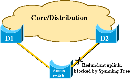
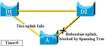
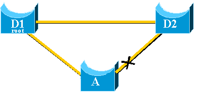
This diagram illustrates a typical redundant network design. Users are connected to an access switch. The access switch is dually attached to two core, or distribution, switches. As the redundant uplink introduces a loop in the physical topology of the network, the Spanning-Tree Algorithm (STA) blocks it.
51a.gif
In the event of failure of the primary uplink to core switch D1, the STP recalculates and eventually unblocks the second uplink to switch D2, therefore it restores connectivity. With the default STP parameters, the recovery takes up to 30 seconds, and with aggressive timer tuning, this lapse of time can be reduced to 14 seconds. The UplinkFast feature is a Cisco proprietary technique that reduces the recovery time further down to the order of one second.
This document details how the standard STP performs when the primary uplink fails, how UplinkFast achieves faster reconvergence than the standard reconvergence procedure, and how to configure UplinkFast. This document does not cover the basic knowledge of STP operation. Refer to Understanding and Configuring Spanning Tree Protocol (STP) on Catalyst Switches in order to learn more about STP operation and configuration:

Uplink Failure Without Uplink Fast Enabled

In this section, refer to the previous diagram, which uses a minimal backbone. The behavior of the STP is inspected in the event of uplink failure. Each step is followed with a diagram.
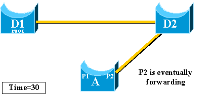
D1 and D2 are core switches. D1 is configured as the root bridge of the network. A is an access switch with one of its uplinks in blocking mode
  1. Assume that the primary uplink from A to D1 fails.
    51b.gif
  2. Port P1 goes down immediately and switch A declares its uplink to D1 as down.
    Switch A considers its link to D2, which still receives BPDUs from the root, as an alternate root port. Bridge A can start to transition port P2 from the blocking state to the forwarding state. In order to achieve this, it has to go through the listening and learning stages. Each of these stages last forward_delay (15 seconds by default), and holds port P2 blocking for 30 seconds.
  3. Once port P2 reaches the forwarding state, the network connectivity is re-established for hosts attached to switch A.
    The network outage lasted 30 seconds.
    51d.gif
    The minimum value allowed for the forward_delay timer is seven seconds. Tuning the STP parameters can lead to a recovery time of 14 seconds. This is still a noticeable delay for a user, and this kind of tuning should be done with caution. This section of this document shows how UplinkFast dramatically reduces the downtime.

Uplink Fast Theory of Operation

The UplinkFast feature is based on the definition of an uplink group. On a given switch, the uplink group consists in the root port and all the ports that provide an alternate connection to the root bridge. If the root port fails, which means if the primary uplink fails, a port with next lowest cost from the uplink group is selected to immediately replace it.
This diagram helps to explain on what the UplinkFast feature is based:
51e.gif
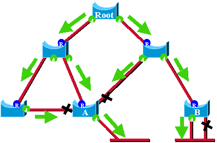
In this diagram, root ports are represented with a blue R and designated ports are represented with a green d. The green arrows represent the BPDUs generated by the root bridge and retransmitted by the bridges on their designated ports. Without the entrance a formal demonstration, you can determine these about BPDUs and ports in a stable network:
  • When a port receives a BPDU, it has a path to the root bridge. This is because BPDUs are originated from the root bridge. In this diagram, check switch A: three of its ports are receiving BPDUs, and three of its ports lead to the root bridge. The port on A that sends BPDU is designated and does not lead to the root bridge.
  • On any given bridge, all ports that receive BPDUs are blocking, except the root port. A port that receives a BPDU leads to the root bridge. If you had a bridge with two ports leading to the root bridge, you have a bridging loop.
  • A self-looped port does not provide an alternate path to the root bridge. See switch B in the diagram. Switch B blocked port is self-looped, which means that it cannot receive its own BPDUs. In this case, the blocked port does not provide an alternate path to the root.
On a given bridge, the root port and all blocked ports that are not self-looped form the uplink group. This section describes step-by-step how UplinkFast achieves fast convergence with the use of an alternate port from this uplink group.
Note: UplinkFast only works when the switch has blocked ports. The feature is typically designed for an access switch that has redundant blocked uplinks. When you enable UplinkFast, it is enabled for the entire switch and cannot be enabled for individual VLANs.

Uplink Failure With Uplink Fast Enabled

This section details the steps for UplinkFast recovery. Use the network diagram that was introduced at the beginning of the document.

Immediate Switch Over to the Alternate Uplink

51f.gif
Complete these steps for an immediate switch over to the alternate uplink:
  1. The uplink group of A consists of P1 and its non-self-looped blocked port, P2.
  2. When the link between D1 and A fails, A detects a link down on port P1.
    It knows immediately that its unique path to the root bridge is lost, and other paths are through the uplink group, for example, port P2 , which is blocked.
    51g.gif
  3. A places port P2 in forwarding mode immediately, thus it violates the standard STP procedures.
    There is no loop in the network, as the only path to the root bridge is currently down. Therefore, recovery is almost immediate.
    51h.gif

CAM Table Update

Once UplinkFast has achieved a fast-switchover between two uplinks, the Content-Addressable Memory (CAM) table in the different switches of the network can be momentarily invalid and slow down the actual convergence time.
In order to illustrate this, two hosts are added, named S and C, to this example:
51j.gif
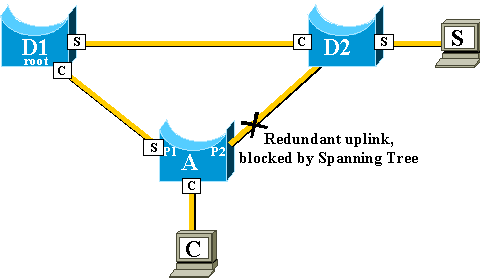
The CAM tables of the different switches are represented in the diagram. You can see that, in order to reach C, packets originated from S have to go through D2, D1, and then A.
As shown in this diagram, the backup link is brought up:
51k.gif
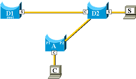
The backup link is brought up so quickly, however, that the CAM tables are no longer accurate. If S sends a packet to C, it is forwarded to D1, where it is dropped. Communication between S and C is interrupted as long as the CAM table is incorrect. Even with the topology change mechanism, it can take up to 15 seconds before the problem is solved.
In order to solve this problem, switch A begins to flood dummy packets with the different MAC addresses that it has in its CAM table as a source. In this case, a packet with C as a source address is generated by A. Its destination is a Cisco proprietary multicast MAC address that ensures that the packet is flooded on the whole network and updates the necessary CAM tables on the other switches.
51m.gif
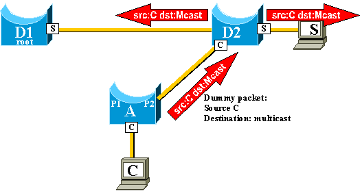
The rate at which the dummy multicasts are sent can be configured.

New Uplink Added

In the event of failure of the primary uplink, a replacement is immediately selected within the uplink group. What happens when a new port comes up, and this port, in accordance with STP rules, should rightfully become the new primary uplink (root port)? An example of this is when the original root port P1 on switch A goes down, port P2 takes over, but then port P1 on switch A comes back up. Port P1 has the right to regain the root port function. Should UplinkFast immediately allow port P1 to take over and put P2 back in blocking mode?
51n.gif
No. An immediate switchover to port P1, which immediately blocks port P2 and put port P1 in forwarding mode, is not wanted, for these reasons:
  • Stability—if the primary uplink is flapping, it is better to not introduce instability in the network by re-enabling it immediately. You can afford to keep the existing uplink temporarily.
  • The only thing UplinkFast can do is to move port P1 in forwarding mode as soon as it is up. The problem is that the remote port on D1 also goes up and obeys the usual STP rules.
    51o.gif
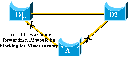
Immediately blocking port P2 and moving port P1 to forwarding does not help in this case. Port P3 does not forward before it goes through the listening and learning stages, which take 15 seconds each by default.
The best solution is to keep the current uplink active and hold port P1 blocked until port P3 begins forwarding. The switchover between port P1 and port P2 is then delayed by 2*forward_delay + 5 seconds (which is 35 seconds by default). The five seconds leave time for other protocols to negotiate, for example, DTP of EtherChannel.

Uplink Failure Repeated After Primary Uplink is Brought Back Up

When the primary uplink comes back up, it is first kept blocked for about 35 seconds by uplinkfast, before it is immediately switched to a forwarding state, as was explained previously. This port is not able to do another uplinkfast transition for roughly the same period of time. The idea is to protect against a flapping uplink that keeps triggering UplinkFast too often, and can cause too many dummy multicasts to be flooded through the network

Changes Implied by Uplink Fast

In order to be effective, the feature needs to have blocked ports that provides redundant connectivity to the root. As soon as Uplink Fast is configured on a switch, switch automatically adjusts some STP parameters in order to help achieve this:
  • The bridge priority of the switch is increased to a significantly higher value than the default. This ensures that the switch is not likely to be elected root bridge, which does not have any root ports (all ports are designated).
  • All the ports of the switch have their cost increased by 3000. This ensures that switch ports are not likely be elected designated ports.
warning Warning: Be careful before you configure Uplink Fast feature because the automatic changes of STP parameters can change the current STP topology.

Uplink Fast Feature Limitations and Interfacing with Other Features

Sometimes a Switching hardware or software feature causes the UplinkFast feature not to function properly. These are some examples of these limitations.
  • Uplink fast does not do the fast transition during a High Availability supervisor switchover on 6500/6000 switches that run CatOS. When the root port is lost on failed-resetting supervisor, the situation after a switchover is similar to when the switch boots up the first time because you do not sync the root port information between Supervisors. High Availability (HA) maintains only spanning tree port state, not the root port information, so when the HA switchover occurs, the new sup has no idea that it has lost a port on one of the uplink ports of the failed supervisor. A common workaround is the use of a port channel (EtherChannel). Root port status is maintained when a Port Channel is built across both supervisors, 1/1-2/1 or 1/2-2/2, for example, or root port is on the port of any Line Card. As no spanning tree topology change occurs when failing-resetting the active supervisor, no UplinkFast transition is necessary.
  • Uplink fast does not do the fast transition during an RPR or RPR+ switchover on a 6500/6000 switch that runs Cisco IOS System Software. There is no workaround because Layer 2 port must go through spanning tree convergence states of listening, learning, and forwarding.
  • Uplink fast implementation on gigastack of 2900/3500XL/2950/3550/3560/3750 is called Cross Stack Uplink Fast Feature (CSUF), general UplinkFast feature on gigastack setup is not supported. CSUF does not implement generation of dummy multicast packets after UplinkFast transition for the update of CAM tables.
  • Do not change spanning tree priority on the switch when UplinkFast is enabled because, it depends on the platform, and it can cause UplinkFast feature to be disabled, or it can cause a loop as the UplinkFast feature automatically changes the priority to a higher value in order to prevent the switch from becoming Root Bridge.

Uplink Fast Configuration

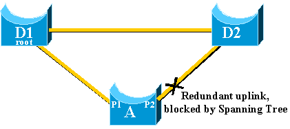
This section gives a step-by-step example of UplinkFast configuration and operation. Use this network diagram:
51p_new.gif
Switches A, D1, and D2 are all Catalyst switches that support the UplinkFast feature. Focus on switch A, while you perform these steps:
Note: Here, the configuration is tested with switch A that runs CatOS and Cisco IOS software.

Viewing the STP Parameter Default

These are the default parameters that are set for the STP on our access switch A:
Note: Port that connects to switch D2 is currently blocking, the current cost value for the ports depends on the bandwidth, for example, 100 for an Ethernet port, 19 for a Fast Ethernet port, 4 for a Gigabit Ethernet port, and the priority of the bridge is the default 32768.
CatOS
A>(enable) show spantree
VLAN 1
Spanning tree enabled
Spanning tree type          ieee

Designated Root             00-40-0b-cd-b4-09
Designated Root Priority    8192
Designated Root Cost        100
Designated Root Port        2/1
Root Max Age   20 sec    Hello Time 2  sec   Forward Delay 15 sec

Bridge ID MAC ADDR          00-90-d9-5a-a8-00
Bridge ID Priority          32768
Bridge Max Age 20 sec    Hello Time 2  sec   Forward Delay 15 sec

Port                     Vlan Port-State    Cost  Priority Portfast   Channel_id
------------------------ ---- ------------- ----- -------- ---------- ----------
 1/1                     1    not-connected    19       32 disabled   0         
 1/2                     1    not-connected    19       32 disabled   0         
 2/1                     1    forwarding      100       32 disabled   0

!--- Port connecting to D1
         
 2/2                     1    blocking        100       32 disabled   0

!--- Port connecting to D2

 2/3                     1    not-connected   100       32 disabled   0         
 2/4                     1    not-connected   100       32 disabled   0         
 2/5                     1    not-connected   100       32 disabled   0         
<snip>
Cisco IOS
A#show spanning-tree 

VLAN0001
  Spanning tree enabled protocol ieee
  Root ID    Priority    8193
             Address     0016.4748.dc80
             Cost        19
             Port        130 (FastEthernet3/2)
             Hello Time   2 sec  Max Age 20 sec  Forward Delay 15 sec

  Bridge ID  Priority    32768
             Address     0009.b6df.c401
             Hello Time   2 sec  Max Age 20 sec  Forward Delay 15 sec
             Aging Time 300

Interface        Role Sts Cost      Prio.Nbr Type
---------------- ---- --- --------- -------- --------------------------------
Fa3/1            Altn BLK 19        128.129  P2p

!--- Port connecting to D2
 
Fa3/2            Root FWD 19        128.130  P2p

!--- Port connecting to D1

Configure Uplink Fast and Check the Changes In the STP Parameters

CatOS
You enable UplinkFast on switch A with the set spantree uplinkfast enable command. These parameters are set:
A>(enable) set spantree uplinkfast enable
VLANs 1-1005 bridge priority set to 49152.
The port cost and portvlancost of all ports set to above 3000.
Station update rate set to 15 packets/100ms.
uplinkfast all-protocols field set to off.
uplinkfast enabled for bridge.
Use the show spantree command and you can see the main changes:
  • the priority of the bridge has increased to 49152
  • the cost of the ports has increased by 3000
A>(enable) show spantree
VLAN 1
Spanning tree enabled
Spanning tree type          ieee

Designated Root             00-40-0b-cd-b4-09
Designated Root Priority    8192
Designated Root Cost        3100
Designated Root Port        2/1
Root Max Age   20 sec    Hello Time 2  sec   Forward Delay 15 sec

Bridge ID MAC ADDR          00-90-d9-5a-a8-00
Bridge ID Priority          49152
Bridge Max Age 20 sec    Hello Time 2  sec   Forward Delay 15 sec

Port                     Vlan Port-State    Cost  Priority Portfast   Channel_id
------------------------ ---- ------------- ----- -------- ---------- ----------
 1/1                     1    not-connected  3019       32 disabled   0         
 1/2                     1    not-connected  3019       32 disabled   0         
 2/1                     1    forwarding     3100       32 disabled   0         
 2/2                     1    blocking       3100       32 disabled   0         
 <snip>
Cisco IOS
You can use the command spanning-tree uplinkfast in order to enable UplinkFast on switch A. These parameters are set:
A(config)#spanning-tree uplinkfast
Use the show spanning-tree command and you can see the main changes:
  • the priority of the bridge has increased to 49152
  • the cost of the ports has increased by 3000
A(config)#do show spanning-tree 

VLAN0001
  Spanning tree enabled protocol ieee
  Root ID    Priority    8193
             Address     0016.4748.dc80
             Cost        3019
             Port        130 (FastEthernet3/2)
             Hello Time   2 sec  Max Age 20 sec  Forward Delay 15 sec

  Bridge ID  Priority    49152
             Address     0009.b6df.c401
             Hello Time   2 sec  Max Age 20 sec  Forward Delay 15 sec
             Aging Time 300
  Uplinkfast enabled

Interface        Role Sts Cost      Prio.Nbr Type
---------------- ---- --- --------- -------- --------------------------------
Fa3/1            Altn BLK 3019      128.129  P2p 
Fa3/2            Root FWD 3019      128.130  P2p

Increase the Logging Level on Switch A In Order to See the STP Debugging Information

CatOS
Use the set logging level command and increase the logging level for the STP, so that you can have detailed information displayed on the screen during the test:
A>(enable) set logging level spantree 7
System logging facility  for this session set to severity 7(debugging)
A>(enable)
Cisco IOS
Use the logging console debugging command and set the console logging of messages at the debugging level, which is the least severe level and which displays all logging messages.
A(config)#logging console debugging

Unplug the Primary Uplink Between A and D1

CatOS
At this stage, unplug the cable between A and D1. In the same second, you can see the port connect to D1 that goes down and the port connect to D2 that is transferred immediately into forwarding mode:
2000 Nov 21 01:34:55 %SPANTREE-5-UFAST_PORTFWD: Port 2/2 in vlan 1 moved to
forwarding(UplinkFast)
2000 Nov 21 01:34:55 %SPANTREE-6-PORTFWD: Port 2/2 state in vlan 1 changed to forwarding
2000 Nov 21 01:34:55 %SPANTREE-7-PORTDEL_SUCCESS:2/1 deleted from vlan 1 (LinkUpdPrcs)
Use the show spantree command in order to check that you have immediately updated the STP:
A>(enable) show spantree
<snip>
Port                     Vlan Port-State    Cost  Priority Portfast   Channel_id
------------------------ ---- ------------- ----- -------- ---------- ----------
 1/1                     1    not-connected  3019       32 disabled   0         
 1/2                     1    not-connected  3019       32 disabled   0         
 2/1                     1    not-connected  3100       32 disabled   0         
 2/2                     1    forwarding     3100       32 disabled   0         
<snip>
Cisco IOS
A#
00:32:45: %SPANTREE_FAST-SP-7-PORT_FWD_UPLINK: VLAN0001 FastEthernet3/1 moved to Forwarding (UplinkFast).
A#
Use the show spanning-tree command in order to check updated STP information:
A#show spanning-tree 

VLAN0001
  Spanning tree enabled protocol ieee
  Root ID    Priority    8193
             Address     0016.4748.dc80
             Cost        3038
             Port        129 (FastEthernet3/1)
             Hello Time   2 sec  Max Age 20 sec  Forward Delay 15 sec

  Bridge ID  Priority    49152
             Address     0009.b6df.c401
             Hello Time   2 sec  Max Age 20 sec  Forward Delay 15 sec
             Aging Time 15 
  Uplinkfast enabled

Interface        Role Sts Cost      Prio.Nbr Type
---------------- ---- --- --------- -------- --------------------------------
Fa3/1            Root FWD 3019      128.129  P2p 

Plug Back the Primary Uplink

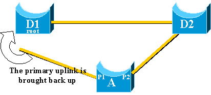
At this point, the primary uplink is manually plugged in and put back up. You can see that the UplinkFast feature forces the port into a blocking mode, whereas usual STP rules have put it in listening mode. At the same time, port that connects to D2, which should go immediately into blocking mode according to the standard STP, is kept in forwarding mode. UplinkFast forces the current uplink to stay up until the new one is fully operational:
CatOS
A>(enable) 2000 Nov 21 01:35:38 %SPANTREE-6-PORTBLK: Port 2/1
state in vlan 1 changed to blocking
2000 Nov 21 01:35:39 %SPANTREE-5-PORTLISTEN: Port 2/1 state in vlan 1 changed to listening
2000 Nov 21 01:35:41 %SPANTREE-6-PORTBLK: Port 2/1 state in vlan 1 changed to
blocking

A>(enable) show spantree
<snip>
Port                     Vlan Port-State    Cost  Priority Portfast   Channel_id
------------------------ ---- ------------- ----- -------- ---------- ----------
<snip>
 2/1                     1    blocking       3100       32 disabled   0         
 2/2                     1    forwarding     3100       32 disabled   0         
<snip>
A>(enable)
35 seconds after the port that connects to D1 is brought up, UplinkFast switches the uplinks, blocks port to D2 and moves port to D1 directly into forwarding mode:
2000 Nov 21 01:36:15 %SPANTREE-6-PORTBLK: Port 2/2
state in vlan 1 changed to blocking
2000 Nov 21 01:36:15 %SPANTREE-5-UFAST_PORTFWD: Port 2/1 in vlan 1 moved to
forwarding(UplinkFast)
2000 Nov 21 01:36:15 %SPANTREE-6-PORTFWD: Port 2/1 state in vlan 1 changed to forwarding

A>(enable) show spantree
<snip>
Port                     Vlan Port-State    Cost  Priority Portfast   Channel_id
------------------------ ---- ------------- ----- -------- ---------- ----------
<snip>    
 2/1                     1    forwarding     3100       32 disabled   0         
 2/2                     1    blocking       3100       32 disabled   0         
<snip>
Cisco IOS
A#show spanning-tree

VLAN0001
  Spanning tree enabled protocol ieee
  Root ID    Priority    8193
             Address     0016.4748.dc80
             Cost        3038
             Port        129 (FastEthernet3/1)
             Hello Time   2 sec  Max Age 20 sec  Forward Delay 15 sec

  Bridge ID  Priority    49152
             Address     0009.b6df.c401
             Hello Time   2 sec  Max Age 20 sec  Forward Delay 15 sec
             Aging Time 300
  Uplinkfast enabled

Interface        Role Sts Cost      Prio.Nbr Type
---------------- ---- --- --------- -------- --------------------------------
Fa3/1            Root FWD 3019      128.129  P2p
Fa3/2            Altn BLK 3019      128.130  P2p

A#
01:04:46: %SPANTREE_FAST-SP-7-PORT_FWD_UPLINK: VLAN0001 FastEthernet3/2 moved to
 Forwarding (UplinkFast).

A#show spanning-tree

VLAN0001
  Spanning tree enabled protocol ieee
  Root ID    Priority    8193
             Address     0016.4748.dc80
             Cost        3019
             Port        130 (FastEthernet3/2)
             Hello Time   2 sec  Max Age 20 sec  Forward Delay 15 sec

  Bridge ID  Priority    49152
             Address     0009.b6df.c401
             Hello Time   2 sec  Max Age 20 sec  Forward Delay 15 sec
             Aging Time 300
  Uplinkfast enabled

Interface        Role Sts Cost      Prio.Nbr Type
---------------- ---- --- --------- -------- --------------------------------
Fa3/1            Altn BLK 3019      128.129  P2p
Fa3/2            Root FWD 3019      128.130  P2p

Disable and Clear the Uplink Fast Feature From the Switch

CatOS
Use the set spantree uplinkfast disable command in order to disable UplinkFast. Only the feature is disabled when this command is issued. All the tuning that is done on the port cost and switch priority remains unchanged:
A>(enable) set spantree uplinkfast disable
uplinkfast disabled for bridge.
Use clear spantree uplinkfast to return stp parameters to default.
A>(enable) show spantree
VLAN 1
Spanning tree enabled
Spanning tree type          ieee

Designated Root             00-40-0b-cd-b4-09
Designated Root Priority    8192
Designated Root Cost        3100
Designated Root Port        2/1
Root Max Age   20 sec    Hello Time 2  sec   Forward Delay 15 sec

Bridge ID MAC ADDR          00-90-d9-5a-a8-00
Bridge ID Priority          49152
Bridge Max Age 20 sec    Hello Time 2  sec   Forward Delay 15 sec

Port                     Vlan Port-State    Cost  Priority Portfast   Channel_id
------------------------ ---- ------------- ----- -------- ---------- ----------
 1/1                     1    not-connected  3019       32 disabled   0         
 1/2                     1    not-connected  3019       32 disabled   0         
 2/1                     1    forwarding     3100       32 disabled   0         
 2/2                     1    blocking       3100       32 disabled   0
 <snip>
Use the clear spantree uplinkfast command. This command not only disables the feature, but also resets the parameters:
A>(enable) clear spantree uplinkfast
This command will cause all portcosts, portvlancosts, and the 
bridge priority on all vlans to be set to default.
Do you want to continue (y/n) [n]? y
VLANs 1-1005 bridge priority set to 32768.
The port cost of all bridge ports set to default value.
The portvlancost of all bridge ports set to default value.
uplinkfast all-protocols field set to off.
uplinkfast disabled for bridge.
A>(enable) show spantree
VLAN 1
Spanning tree enabled
Spanning tree type          ieee

Designated Root             00-40-0b-cd-b4-09
Designated Root Priority    8192
Designated Root Cost        100
Designated Root Port        2/1
Root Max Age   20 sec    Hello Time 2  sec   Forward Delay 15 sec

Bridge ID MAC ADDR          00-90-d9-5a-a8-00
Bridge ID Priority          32768
Bridge Max Age 20 sec    Hello Time 2  sec   Forward Delay 15 sec

Port                     Vlan Port-State    Cost  Priority Portfast   Channel_id
------------------------ ---- ------------- ----- -------- ---------- ----------
 1/1                     1    not-connected    19       32 disabled   0         
 1/2                     1    not-connected    19       32 disabled   0         
 2/1                     1    forwarding      100       32 disabled   0         
 2/2                     1    blocking        100       32 disabled   0
 <snip>
Cisco IOS
Use the no spanning-tree uplinkfast command in order to disable UplinkFast. In Cisco IOS switches, unlike CatOS switches, all the tuning that is done on the port cost and switch priority revert to the old values automatically at this point:
A(config)#no spanning-tree uplinkfast
A(config)#do show spanning-tree 

VLAN0001
  Spanning tree enabled protocol ieee
  Root ID    Priority    8193
             Address     0016.4748.dc80
             Cost        19
             Port        130 (FastEthernet3/2)
             Hello Time   2 sec  Max Age 20 sec  Forward Delay 15 sec

  Bridge ID  Priority    32768
             Address     0009.b6df.c401
             Hello Time   2 sec  Max Age 20 sec  Forward Delay 15 sec
             Aging Time 15 

Interface        Role Sts Cost      Prio.Nbr Type
---------------- ---- --- --------- -------- --------------------------------
Fa3/1            Altn BLK 19        128.129  P2p 
Fa3/2            Root FWD 19        128.130  P2p

Conclusion

The UplinkFast feature dramatically decreases the convergence time of the STP in the event of the failure of an uplink on an access switch. UplinkFast interacts with other switches that have a strict standard STP. UplinkFast is only effective when the configured switch has some non-self-looped blocked ports. In order to increase the chances to have blocked ports, the port cost and bridge priority of the switch are modified. This tuning is consistent for an access switch, but is not useful on a core switch.
UplinkFast only reacts to direct link failure. A port on the access switch must physically go down in order to trigger the feature. Another Cisco proprietary feature, Backbone Fast, can help to improve convergence time of a bridged network in case of indirect link failure.

Command Reference

Related Information